 |
 |
[1] |
CONFIGURING THE MOTHERBOARD |
Components use jumpers for configuration. A jumper is a pair of tiny pins that is left
covered or uncovered by a block of plastic with metal inside. This acts as a switch to tell the
computer that a certain component is "on" or "off". Before you mount a motherboard inside a computer,
you must configure the motherboard so that it complies with all the components you wish to connect
to it. Common uses for jumpers include processor speed, internal\external battery selection, and enabling\disabling
an on-board video card. The best reference to use when configuring your motherboard is the manual that came with it.
|
 |
 |
[2] |
MOTHERBOARD PLACEMENT |
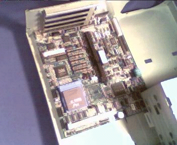
Once you have set up the motherboard for use, fit it inside the computer's casing. Line up the screwholes on
the motherboard with the mounting brackets on the casing.
|
 |
 |
[3] |
MOTHERBOARD MOUNTING |
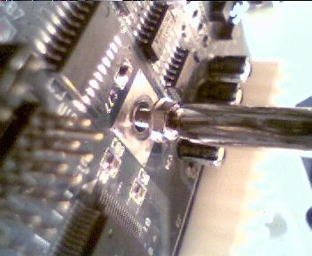
Once you have properly placed the motherboard, screw it into place.
|
 |
 |
[4] |
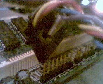
MEMORY INSTALLATION |
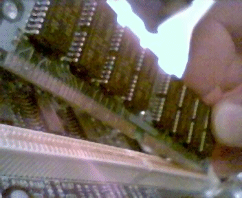
There is a very broad range of types of memory. Each type must be installed in its own way. Consult the
documentation of your PC and your memory to find which installation method best suits your equipment.
|
 |
 |
[5] |
FRONT PANEL CONNECTORS |
The LEDs on the front of your computer typically connect to the front of the motherboard. Fit these pins into
their proper locations. There are many variations of arrangements. Consult your motherboard documentation to find
what goes where.
|
 |
 |
[6] |
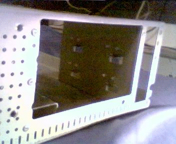
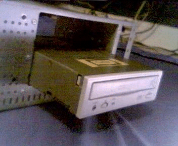
DRIVE BAYS |
Computer cases feature several areas called bays that allow the placement of a CD-ROM, hard disk, floppy drive, and
so on. Two common sizes are 5.25 inch and 3.5 inch. Computer drives slide into these bays, and on drives such as floppy drives
or CD-ROMs, the face of the drive points outward so that the user may exchange media within the drive via floppy disks or compact discs.
|
 |
 |
[7] |
DRIVE INSTALLATION |
To install a drive, gently slide it into the bay you wish to place it in. If your drive is a CD-ROM, floppy disk,
or other drive that uses removable media, select a bay in which the casing provides an opening for, so that you may
access the drive freely. If your drive is a hard drive, select a bay in which the casing provides no opening for,
as there is no need to freely access the front of a hard disk, since its media is fixed.
|
 |
 |
[8] |
DRIVE MOUNTING |
Once the drive is fitted in place, gently screw the drive into the mounting bracket where the screwholes
and mounting brackets line up.
|
 |
 |
[9] |
MORE DRIVE INSTALLATION |
Use this same method for as many drives as you like. Many computers provide several bays for all sorts of drives,
so you can build your computer to best suit your needs.
|
 |
 |
[10] |
HARD DRIVE INSTALLATION |
Hard disks, along with CD-ROMs, must be configured and put in boot order. Consult your equipment documentation to find
out how to do this with your product. Anywho, configuring hard drives (and CD-ROM drives) uses jumpers, just like
motherboard configuration above.
|
 |
 |
[11] |
SETTING UP MORE DRIVES |
Once you have finished the drive installation, make sure they are properly mounted. The next step
will cover connecting these drives to the motherboard.
|
 |
 |
[12] |
CONNECTING FLOPPY DRIVES |
Floppy diskette drives are connected to the motherboard using special 25-pin cables. To sum up the installation
of floppy drives, line pin 1 up with the red stripe on the cable. A general rule is that the red stripe on the cable
will be closest to the power connector of the drive.
|
 |
 |
[13] |
CONNECTING IDE DRIVES |
IDE drives (hard disks, CD-ROMS) use the same basic method as floppy drives, only the cable is referred to as 40-pin.
Follow the same steps to connect the cable to the IDE drive.
|
 |
 |
[14] |
CD-ROM Audio |
CD-ROMS provide a connection to play audio discs directly through the sound card. There are many types of
cables and connectors that vary between the sound card and CD-ROM drive.
|
 |
 |
[15] |
POWER SUPPLY PLACEMENT |
Gently slide the power supply into its proper position in the computer casing. Make sure the items on the
rear of the supply (fan, power plug, etc.) are properly lined up with the computer casing openings.
|
 |
 |
[16] |
POWER SUPPLY MOUNTING |
Carefully screw the power supply to the computer casing at all required places. Also make sure the power supply is
set to the correct voltage.
|
 |
 |
[17] |
POWER CONNECTORS |
There are several connectors that come from a power supply: motherboard power connectors, processor fan power connectors, drive power connectors, etc.
The two types of drive connectors are shown here.
|
 |
 |
[18] |
5.25" POWER CONNECTORS |
Connect the larger of the two drive power connectors to drives with this size power jack.
|
 |
 |
[19] |
3.5" POWER CONNECTORS |
Connect the smaller of the two drive power connectors to drives with this size power jack.
|
 |
 |
[20] |
DRIVE CONNECTION |
By now, the computer's drives have cables coming off them, and the power supply has been connected to all of the drives.
Notice the 25-pin and 40-pin connectors on the motherboard. Connect the floppy drives and IDE drives to them, respectively.
If your motherboard has more than one IDE connector, make sure your primary drives are going into the primary IDE connector,
and that your secondary drives are going into the secondary IDE connector.
|
 |
 |
[21] |
MOTHERBOARD POWER |
Connect the power supply to the motherboard.
|
 |
 |
[22] |
PERIPHERAL CARDS |
Computers have an area in which peripheral cards may be installed. Most computers today have a variety of
connections for the cards to be inserted into, and many cards can be installed at the same time.
|
 |
 |
[23] |
PERIPHERAL CARD INSTALLTION |
To install a peripheral card such as a sound card or modem, find an available slot with the corresponding bus type.
Remove the slot cover, and gently insert the card into the slot.
|
 |
 |
[24] |
PERIPHERAL CARD MOUNTING |
Now that the card is installed, it must be secured to the computer chassis. Use the screw from the slot's cover
and screw the card into place.
|
 |
 |
[25] |
CASE PLACEMENT |
Gently fit the case onto the computer chassis, and slide it all the way back. Many cases vary, however, and the case
might be placed differently.
|
 |
 |
[26] |
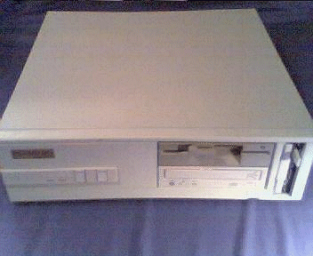
CASE MOUTNING |
Carefully screw the computer case to the chassis in all required spots.
|
 |
 |
[27] |
THE FINISH LINE |
These steps were very basic. Many computers today require additional steps, such as processor fans, additional power
supply connectors, and much more. As always, consult your equipment's documentation for the proper construction of
your computer.
|